Jeff Knorek, a fellow railfan and photographic Compatriot, and myself were discussing web sites in late April 2002. I asked him..."What makes a good web site?" He responded (paraphrasing), "Web Sites that explain in the simplest terms an area or anything else. There are a ton of web sites that simply don't accomplish this task. Many are just a collection of technical knowledge and the creator assumes you know the subject."
Well, if you read this Jeff.....here is your advice in html!
SEND THE AUTHOR A MESSAGE HERE
The Diesel Engine has been around for nearly 120 years, first invented by Dr. Rudolph Diesel in Germany. Diesel, the namesake, first produced the 2-cycle engine and then later the 4-cycle engine. This engine wasn't adopted for North American Rail usage until 1918 when the General Electric/Ingersol-Rand/American Locomotive Company (ALCo--itself a freshly created union of seven steam builders) venture build the first commercial application for a small transfer Railroad in New York City named "Jay Street Connecting." Various units were produced and experimented with until the 1930s in the role of a switcher as Railroads saw these engines with an unreliable eye. The trend started to shift when Electro-Motive Company (EMC), a small firm in Cleveland, was formed ca.1922. The Company was originally just an engineering firm that contracted all work to local manufacturers. Eight years later, this engineering firm had caught the eye of General Motors, itself a young Automobile maker, and was brought into the GM family as Electro-Motive Division (EMD). EMD itself was formed by EMC and Winton Engines, a company that EMC had contracted to build engines. EMD stayed in Cleveland, but moved its major operations to La Grange, Illinois. EMD is the company that really revolutionized the face of American railroading....first with the Full Body Streamlined E and F units, then with Richard Dilworth's Utilitarian GP and later SD series. EMD enjoyed overwhelming market success until the mid-1980s when General Electric took the majority market share.
However, it is important to note the other smaller Diesel Builders that made their mark on the Industry. ALCo, the former GE partner, has always been the underdog's favorite. The niche builder within the locomotive industry. ALCo to some was the ultimate builder that has been forgotten. ALCo was responsible for many great engine improvements, but they were always reacting to other builders.
ALCo wasn't alone...it was a rough and ready time to build Diesel Locomotives post-WWII. In 1952, Diesel Locomotive production equalled Steam Engine production, while Electric Locomotive production was a distant third. The steam builders were forced into a transition: Baldwin (the largest Steam Locomotive builder), Fairbanks-Morse (a very successful Marine engine builder for the United States Navy), and Lima-Hamilton (which would later merge with Baldwin).
Fairbanks-Morse still exists today building marine Diesel Engines for the Untied States Navy and the commercial market. F-M was considered to be the premier Diesel Builder in US when it entered the market with its opposed Piston design, F-Ms truly unique trademark...and its ultimate demise. This engine was unlike anything else produced for the Locomotive application, so the Railroads had a hard time maintaining these units. F-M also retains the distinct achievement of having the most powerful Locomotive on the market at the time of its departure...the H-24-66, or TRAINMASTER. This unit was so powerful, that the railroads thought the Locomotive was OVERPOWERED. One can only imagine what barriers F-M could've broke if they remained in the market.
Baldwins early success, and arguably their only success, came in the VO1000. This Locomotive was a very popular switcher and enjoyed decent sales in the United States of America. Baldwin had later success with its ASA616 design, but this didn't provide enough cash for the Bankrupt company. However, prior to its downfall, Baldwin managed to merge with another transitional builder, Lima-Hamilton. Lima Locomotive Works (LLW), located in Lima, Ohio, was a Steam Engine builder of the three-truck Shay fame. Hamilton Diesel (HD), located in my hometown of Hamilton, Ohio, was a Diesel engine builder for the United States Navy mainly. When LLW and HD merged, Lima-Hamilton was a Diesel/Steam Engine builder, very similar to Baldwin in many regards. During a March 2002 visit to the Whitewater Valley Railroad facilities in Connersville, Indiana , I spoke with William Grey, WVRR Curator about Lima's. He stated that when L-H merged with Baldwin, the company assumed a tremendous debt from Baldwin. This would eventually lead to the company's demise. The WVRR runs a Lima Diesel practically everyday during the season. I asked him how she performs...and he said "Great!". Lima Diesels were tough, hard-nosed engines that could pull anything at slow speeds. In fact, their only slow speed rival would've been ALCo.
There is another Diesel/Steam builder worth mentioning: Porter. I don't know much information about Porter other than they produced smokeless-fireless Steam Engines and Industrial Diesel Locomotives or switchers. A catalog I own talks about Porter Industrial Switchers from the 1940s/1950s, so I do know they were active during the Great Dieselization Period.
After 1969, the Domestic Diesel Market was held by GE and EMD or GMLG (GM combined its Canadian builder with the American EMD to create General Motors Locomotive Group) as they are now known. EMD has always been the leader in Locomotive quality and production until the SD50 of the early 1980s. That is when GE sought a market rebound and accomplished just that when it solidified its market dominance with the Dash 8 series of the late 1980s. Ever since, EMD has been the Number Two builder.
It is important to note, that GE was never considered a main independent builder until it split with ALCo in the mid-1950s. The Universal series established General Electric as an independent Locomotive builder. GE's involvement within the market has always been on the Electrical side. During EMC/EMDs early years, GE supplied many of the Generators and other Electrical components to EMD/EMC. Even after the ALCo/GE split, ALCo still used GE parts until it signed a contract with Westinghouse for the Electrical components. GE has always been a market dominator relating either directly of indirectly to the Diesel Locomotive industry. The only question is: Who will be the next Dominator?
Diesel Locomotives has many visible and invisible parts when we see them whizzing by at speed. The trick is know: What does what and what is that? Many people, railfans included, see a Locomotive and they shrug it off as loud and obnoxious or just plain ugly. While everyone is entitled to their opinion, this is only a skin deep view.
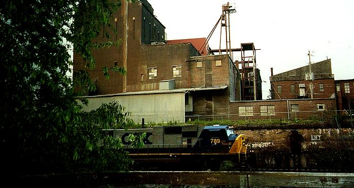
From the picture above, I have pointed out some of the major EXTERNAL parts of the Diesel Locomotive. Each model is unique in some fashion, so the parts/objects above are fairly universal with the exception of the Wide Nose design and the GE-style flared Radiator. Each builder has produced their own version of everything: including body design. There are several good books currently for sale which break down these models in a better individual fashion. A list of RECOMMENDED READING has been provided at the bottom of this page.
Please reference the picture above for the following sections:
CAB
The picture above depicts a General Electric C40-8W (a discussion follows explaining MODEL DESIGNATORS). The front of the Locomotive is on the righthand of the picture. This particular model has a Wide Cab. The wide cab is very similar to the front of the older streamlined Cowl units in that a passage exists through the nose leading into the cab. ALCo, F-M, and BLH never produced Wide Cab versions for American Domestic Markets. Montreal Locomotive Works (MLW), ALCo successor and Canadian licensee, did produce Wide Cab versions for Canadian railroads in a limited capacity. The first Wide Cab post-Utilitarian GP7 design was used on the DDA40X (This is how GMLG lists the models designation) purchased solely by power hungry Union Pacific. The Wide cab has many different names, among these would be Safety Cab, Crew Cab, Comfort Cab, Wide Nose, and Canadian Cab. The larger cab was first ordered and used in the Canadian Market and was offered as a standard. Not until the 1990s were the Wide Cabs offered as standard features on Locomotives for American usage.
The cab itself houses the crew during standard operations. The Engineer (when facing Locomotive front) will be seated on the Right, the Brake man will be on the left, and the Conductor (optional as it is) will be seated cab center. The Cab is the nerve center of the locomotive, containing a majority of the controls neccessary for function and movement. There are also many gauges which report the status of the Locomotives systems to the crew in the Cab. In recent years, Computer technology has taken the human factor out of monitoring these systems, which in a limited sense allows the crew to focus more on operations. Some crews enjoy this feature, while others feel it is the plague. It depends on who you speak with and what they are doing.
Dynamic Brakes were an innovation that came in the 1930s from EMD. Dynamic Brakes use the Traction Motors to slow the engine down by converting Electrical Energy into heat and dissipating this through a series of grids. Large fans then suck air over the Heal Sink to cool the Dynamic Brakes. A better technical explanation cane be found by visiting the RECOMMENDED READING section of this web site. Dynamic Brakes are very similar to throttle settings that you may have heard in passing. These settings determine the maximum amperage that the traction motors will transfer to the Dynamic Brakes. As a general thumb rule for older models, the maximum Dynamic Braking capacity can be determined by multiplying the number of POWERED axles by 10,000 pounds of force. For example, a GP40 has 4 POWERED AXLES, so 4 x 10,000 lbs.=40,000 lbs. This holds true for all non-extended range Dynamic Brake Systems. Given the new AC technology, the capabilities of the Dynamic Brakes has been increased to compensate for the increased power of the new AC Traction Motors.
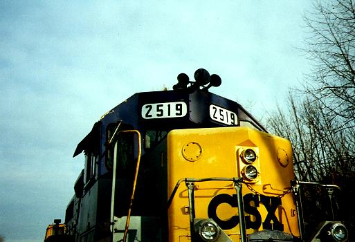
The horn is probably what people hate or recognize first without seeing a Locomotive. Over the years, there have been many different horns produced. For example, Conrail engines have a different Horn sound versus a standard CSX unit. The Horn is Bidirectional facing the front and rear of the Locomotive. The FRA has established standards that determine the maximum source level (or how loud the horn is approx. 1 yard from the horn measured in decibels) for Locomotive horns. Horns are typically used at all Grade crossings and can also be used to communicate with crew members on the ground performing various tasks. The horn on older Locomotive models is located directly above the cab
EXHAUST
This is the external discharge for the Diesel engine. The exhaust dispels the by-product of combustion into the atmosphere. The exhaust on GE Locomotives is located in a different positon when compared with other locomotives.
The Radiator is one of those critical secondary systems that the Locomotive couldn't do without. The Radiator is responsible for primarily cooling the Diesel Engine by using water. General Electric has always used a "wing" at the end of the LONG HOOD to house the Radiator. Over the years, as the Diesel Engines were required to produce more, the Radiator wing has grown. Early U25Bs have very small Radiators wings when compared with the new AC6000CWs, and even when compared against the AC4400CW, the 6000s radiator is much larger. The reason for this growing wing is the growing size of the fan housed within the wing. As a general rule, GE Locomotives have always had ONE radiator fan, as opposed to the other builders who have used multiple radiator fans. Without the radiator fans to cool the hot engine cooling water, the Diesel Engine would overheat and shutdown. Currently, the new Tier Two EPA standards for Diesel locomotives have all but forced GMLG and GE to shutdown Domestic production of Diesel Locomotives. These standards were implemented on January 1, 2002. As a result, GMLG has been testing Tier One compliant SD70Ms on various US Class Ones.
GMLG has located the Radiator in general directly above the Diesel Engine reserving the rear space for the AIR COMPRESSOR system. GMLG has opted for more of a flare on its SD45s in the rear section of the Long Hood. The current SD90MACs have a large "wing" located in the middle of the long hood. Earlier EMD models had a flush Long hood, so the only distiguishing characteristic of the radiator to be found were the raised fan caps.
Without the trucks,the Locomotive could never go anywhere. Over the past 80+ years, there have been many different truck designs leading to a variety of different designators. To understand these designators, it is important to understand what the truck does.
The truck is basically very similar to the front and rear axle of an Automobile, the big difference being the truck holds many axles. The truck is where all of the Locomotives weight is distributed before once again being distributed to the axles and finally onto the wheels, which contact the railhead. The trucks all bear the weight of the TRACTION MOTORS, which are normally hung from the truck. Far and away, the truck is the heaviest piece on the Locomotive, followed closely by the Diesel Engine itself. There are essential two basic types of trucks: "Cs" or "Bs". To determine this, we must discuss how to determine what kind of category the truck will fall into. In the picture above of the C40-8W, this unit has a set of C trucks. Each axle powered by a traction motor receives a letter (A, B, C, etc.) depending on how many axles are powered on that PARTICULAR truck. Each unpowered truck is given a numeric designation (1, 2, 3, etc.) In the above example, all three axles are powered in each truck, so you would count the powered axles as A, B, C....thus, the highest letter would be a C....or a C Truck. Now take into account the E7A, a three axle truck design, with two powered axles. Only the outside axles are powered on the E7A, so this were the Designation gets tricky. Since the first axle is powered, it receives an "A", the center axle is unpowered, so it receives a "1", and the last axle is powered, so it receives an "A"......so, the designation would be A-1-A. The trick is this: the axles are counted in sets on the truck. For example, the Centipede built by Baldwin had a wheel arrangement of D+2-2+D. This means that the first four axles are powered, and then the last two are unpowered. The reverse is true for the trailing truck. The first two axles are unpowered, while the remaining four are powered. This method can also be used on car trucks...which are generally in a 2-2 arrangement.
Going back to the weight transfer topic in this section, the each truck carries a certain percentage of the entire Locomotives weight, generally/roughly 50% per truck. This weight is then further divided to each axle and the weight is then divided in half to the wheel on each side of the axle. Typically, the maximum rating of Locomotive axles is 70,000 lbs. So, in theory, a four axle Locomotive can't weigh over 270,000 lbs. And a six axle unit over 420,000 lbs. This practical limit is being pushed currently with the new AC units along with there DC Traction counterparts. Not only is it important for the truck to act as a transfer agent for weight, but it also becomes important in terms of traction/adhesion. Locomotives are only as good as their engines, traction motors, and trucks. The trucks must transfer the weight directly in an even fashion to the axles, however, this really doesn't happen. Now, remember those locomotives with unpowered axles....well, that weight is wasted and can't be used to supply the Locomotive with adhesion. Adhesion is basically a percentage of the Locomotives weight that can be transferred into pulling power. While the topic of adhesion is off topic, it is critical to understand given the functionality of the truck. Older Diesel Locomotives could only transfer roughly 10-25% of their weight into pulling power (or Tractive Effort/Drawbar Pull). It must be remembered that weight is a force (Weight=Mass*Gravity) expressed in pounds or Newtons...depending on your national system. This is why the new AC Traction motors become so important: they now have the ability to transfer up to 40% of the Locomotives weight into Tractive Effort.....doubling earlier models! As a ratio, one SD90MAC-H can replace TWO SD40-2s! Or one AC6000CW can replace TWO B30-7s! This is also another reason why Steam engines met their demise, not all of the engines weight was placed on the drivers. Some of the later Steam Engines weighed over 1,000,000 lbs., but their adhesion was low when compared against a lower horsepower Diesel. Not only has this been enables by better Traction Motors, but also by better Truck designs. GMLG is currently producing what is calls its HTCR-II truck. This is a radial truck that is self-steering and is supposed to create a better ride for the crew and decrease rail wear. GE has been using a Trimount design for a number of years. This idea was also used by F-M in their Train master and in the ALCo Century series. Even though the name is the same, they are three completely different designs. The trimount truck is supposed to have three transfer points for the Locomotives weight, as opposed to the older bolster truck, which only had one weight transfer point.
Long Hood
The Long Hood, is on the after portion of the Locomotive and its main function is to protect the internal elements from the external elements. The Long Hood houses the Diesel Engine, Generator, Air Compressor, lube oil pumps, Governor, Fuel oil Pump, Radiator, Dynamic Brakes, and various other smaller systems.The Long Hood really evolved after the GP7 and RS-1 were introduced, but it was mainly derived from the GP7. The earlier F and E units still had the full body, which completely covered the outside walkways along with the everything under the Long Hood. There is also a walkway connecting the left and right passages near the front of the Locomotive.
Air Banks
The Air banks are typically located externally in various places on the Locomotive. The C40-8Ws are located above the Fuel Tank on the Engineer's side of the Locomotive. The Air banks hold reserve air which is used for the sanding valves, locomotive brake air, and the train's brake air.
Fuel Tank
these come in all shapes and sizes.......from 600 gallons to 5,000 gallons....the range is almost limitless. The Fuel Tank is traditionally located on the bottom of the Locomotive and is in the center. To prevent the slosh of Diesel Fuel, baffles or long steel partitions are installed in the fuel tanks to prevent the moving Diesel fuel to begin rocking the Diesel engine to the point of derailment. In older Diesel locomotives, the Fuel Tank often shared space with the Water Tank for the Steam Generator. In the early days, these tanks were often much smaller than their Modern counterparts.
Sand Tubes
Sand, the lifeblood of Adhesion. Without Sand, wet rail would be the Locomotives worst nightmare...without sand, Locomotives would spin there wheels all day on wet leaves. The Sand is blown onto the rails where the wheel contact the railhead to provide grip for the Locomotive. As the wheel slips, the Engineer or Computer system can adjust the amount of sand being applied to the rail head. Without sand, wet days would be even worse!
Couplers
Easily overlooked items, especially since I didn't include them in the picture above. Anyway, the couplers are the glue of the train. Every car should have two couplers, one on each end. The object in the coupler that holds or locks the train together is called the knuckle. If you recall the conversation above which included Tractive Effort....wel, this is where the pulling power of the Locomotive acts directly...through the coupler. The Standard car coupler is designed to withstand 250,000 lbs. of force! While the Locomotive Couplers are designed to withstand 500,000 lbs. of force...oh, and by the way....every Locomotive comes with a few extra couplers! Every so often the expression "I got a knuckle." can be heard around the railroad.......this simply means that the engineer applied too much force (or pulled to hard) and broke or cracked a knuckle. Generally, this is the source of a ton of friendly ribbing between engineers...while the dispatcher is ticked off trying to find a way around this mess.
Internally, the Locomotive is a very dynamic item. While, I provide in-depth information, I will supply a basic listing and function of each item.
Prime Mover
Also, called the Diesel Engine. This is either a 2-stroke or 4-stroke internal combustion engine depending on the Builder. As a rule of thumb, 4-stroke diesels are more efficient than their 2-stroke contemporaries. In fact, part of the new EPA guidelines have outlawed further 2-stroke production. (The new H Block was GMLG's first 4-stroke Engine, directly related to the EPA standards.)
Electrical Generator
The Electrical Generator is connected directly to the Engine. This is where the phrase "Diesel Electric" originates. The Diesel Engine just supplies power to make electricity, so the rest of the engine can operate. Generators in the early years produced DC power, but later switched over to AC Generator Sets in the late 1960s (this is the reason why NS has labelled certain GP38s as GP38AC...it has nothing to do with the traction motors, just the Generator. The Generator will send the electricity to all systems in the engine, including Traction Motors. Diesel Locomotives can be classified by their electrical systems. An AC-DC-AC, system means that the engine has an AC Generator and DC traction Motors. A DC-DC system means that the systems is purely DC, traction Motors and everything else. However, early Diesel Locomotive did have AC alternators included in the system. They produced 74volts for10 Kilowatts. I have not at this writing, discovered the systems which utilized the AC power. Their is also an Auxillary generator which feeds current to the batteries. The Batteries would be used as emergency back-up power.
Air Compressor
the Air Compressor is normally powered by Electricity and supplies air to the Brake System and the Sanding System. The Air Compressor is located in the front portion of the Long Hood on modern GEs and in the rear of Long Hood area on GMLGs. The Air Compressor will also feed air to the Air Banks on the Locomotive, which are used to maintain system air.
System Pumps
There are various system pumps on the Locomotive. The Fuel Pump, Lube Oil pump, and Cooling water Pump are the major items. The Lube Oil and Cooling Water pumps are primarily used to maintain system circulation, while the Fuel Oil Pump is used to supply the cylinders with Diesel Fuel from the Fuel tanks. Until recently, GMLG opted for mechanically driven pumps, while GE used electrical pumps. Currently, GMLG has switched over to all Electrical pumps.
Steam Generator (optional)
The Steam Generator is used specifically for passenger car operation. The GP7s and GP9s were supplied with a Steam Generator as an option for passenger car service. However, since the 1970s, this has been phased out and limited to Diesel Engines built specifically for passenger Service. Currently, this has changed over to the more modern Head-End Power Unit HEP. This is basically a Generator used to supply power to the passenger cars. At one point , every Diesel locomotive (including Switchers) had Steam generators included under the hood before the days of Amtrak and the era of waning passenger service.
Frame
The unseen and probably largest part of the Locomotive. The frame is basically the structure of the Locomotive. A good way to think of a Locomotive frame is to consider a human skeletal system. Were over 200 bones in our body that support and give shape to our various appendages. While, in the same moment, the skeleton gives us strength. Without a skeleton...we would just be a sack of organs and muscles.....a blob. A Locomotive would be the same. The Frame is also responsible for a large amount of the Locomotives weight.
Recalling again the Tractive Effort section under the TRUCKS category. Well, the more a Locomotive weighs...the more it can pull. The bigger the better concept all over again. Well, the frame must support all of that weight, so this item isn't small by any stretch. The Frame runs the Length of a majority of the length of the locomotive along the bottom. So, in reality, the frames acts to give the Locomotive more weight for adhesion and Tractive Effort; lower the Center of Gravity; and support all of the machinery and operators of the Locomotive. A very immobile and inactive piece of the Locomotive puzzle that is extremely crucial.
Cooling System
As I mentioned above in the RADIATOR section, the cooling system is responsible for maintaining the temperature of various engine related systems...mainly the engine. If the engine overheats, then the Locomotive sensors will engage and sut the Locomotive down. The Cooling System uses water to cool the engine and then run that water through the radiator where air is blown over a heat exchanger to cool the water. There are two types of Cooling systems: Split and single. The Single system is one system that runs from the Lube Oil system through the engine and other asscoaited machinery to the radiator. The Split Cooling system will have one portion connected to the radiator and meet the other portion in a water-to-water heat exchanger. I am not sure of the advantage of this system...so if you happen to know...drop me a message at the bottom of the page.
Lube Oil System
This is the life blood of the engine....or any moving machine! Without some sort of lubricant, the engine pistons would sieze in there respective cylinders. This problem would bve caused because of frictiona nd heat...so in effect, the engine would simply weld itself into one large metal mass...another reason for the cooling system. Much liek the oil in an automobile, the oil acts to lubricate all of the internal moving parts of the engine. It has many of the same components, an oil tank, oil pump, and a few oil filters here and there.
Fuel Oil System
The name says it all: Fuel. The Fuel Oil System is responsible for taking the Diesel Fuel from the Fuel tank through the systema nd asscoiated filters before it is sprayed into the cylinder and mixed with air to form an explosion...which drives the piston down the lube oil lined cylinder walls. The Fuel is brought from the Fuel tank by means of the above mentioned Fuel Pump.
GMLG | General Electric | Baldwin | ALCo | MLW | Lima-Hamilton | Fairbanks-Morse |
In this section, I am going to merely list all of the models that were built over the years. Use the in page links provided above to navigate this section. Some of these Locomotives will have technical specifications available on line, so please check the rest of this web site for various models.
EA/B
E1A/B
E2A/B
E3A/B
E4A/B
E5A/B
E6A/B
E7A/B
E8A/B
E9A/B
F-Units
FTA/B
F2A/B
F3A/B
F7A/B
F9A/B
Hybrids
BL1
BL2
C40-9/C40-9W
C44-9W
Evolution Series
ES44DC
Power Diesels
U50C
U50B
ERIE A
ERIE B
H-15-44
H-16-44
H-12-44
H-20-44
H-20-66
H-12-44TS
H-16-64
H-16-64
H-12-64
H-16-66
H-24-66
CFA-16-4/CFB-16-4
CFA-20-4/CFB-20-4
CPA-20-5
CPA-24-5
CPA-16-4CPB-16-4
CPA-16-5/CPB-16-5
P-12-42 (TALGO)
HH600
HH660
HH900
HH1000
S-1/E-1530
S-2/E-1540
S-3/E-1530A
S-4/E-1540A
S-5/DL-421A
S-6/DL-430
T-6/DL-440
MRS-1(RSX-4)/E-1670
MISC.
DH-643/DH-400
The following section can be used in conjunction with the preceding section to decipher Builder Designations for various Models.
GMLG
GP= General Purpose
Usually at the front of the Model Designation. These units will have two axle trucks
SD= Special Duty
Usually at the front of the Designation. These units will have three axle trucks.
DD= Double Duty??
Used to designate units with two engines and D-D trucks.
M= Wide Cab
Usually at the end of the designation.
I= Isolation Cab
Usually at the end of the designation. These units have stabdard cabs with a large isolation gasket which separates the cab from the frame, thus lowering in cab noise levels.
AC= AC Traction Motors
Used to deisgnate units with AC traction Motors. This will also appear on the GP38AC/MP15AC meaning the unit has an AC Generator.
A=Cab Unit.
End designation, refers to the Unit as having a Cab.
B= Cabless Unit
The Unit lacks a Cab, and houses only the engine and associated machinery.
E-Unit= Eighteen Hundred Horsepower
This was the original HP rating of the E-Unit Series, but as technology increased...so did the Horsepower. these units have A1A trucks.
F-Unit= Freight Unit.
Four axle Streamlined Full Body units with B-B wheel Arrangement.
BL= Branchline
The "missing Link" between the F-Units and GP Series. These units are A1A-A1A.
X=Experimental
Used on units utilizing new technology.
-2= Dash 2
Signifies units using Compartmentalized Electronics along with other improvements.
F= Full Body
This is used either in front or behing the Designator to designate a Full Body. This was used later after the F-Units had completed production.
P= Passenger
Used throughout the Model Designators.
SW= Six Hundred, Welded Frame
This was the original designation for Switchers, but later went on to mean simply "Switcher".
SC= Six Hundred HP Switcher, Cast Frame
Old EMC Designation
NC= Nine Hundred HP Switcher, Cast Frame
Old EMC Designation
NW= Nine Hundred HP, Welded Frame
Early EMD Designation
TR= Transfer Switcher
Used to signify switchers with a Cow/Calf combo used in Heavy Haul Switching Operations.
T= Tunnell
Used to signify units with Air Intakes lowered on the body designed specifically for Western Tunnell Operations.
MP=Multi-Purpose
Another EMD Switcher Designation.
RS= Road Switcher
Used for only one unit. RS1325, a super-lightweight switcher.
General Electric
GE uses the units HP in most, if not all cases. For Example, U30B...means 3000 HP. However, AC4400CW, means 4400 HP.
Universal (U), -7, -8, -9= GE Locomotive Improvements.
GE can't really be classified by unit series, but rather unit HP and subsequent improvements. The -9 is the latest improvement in the Dc traction Motor field.
AC= AC Traction Motors
Used in the beginning of the model Designator to distinquish AC Traction Motor Units.
-7 Super
These are upgraded Universal Series Locomotives...rebuilds really.
W=Wide Cab
Generally used at the end of the Designation.
C= truck type
Used to designate Locomotives using C-C Wheel Arrangements.
B= truck Type.
Either at the end of beginning of the model Designator. B-B Wheel Arrangement.
P=Passenger
Recent additon to the designator series. In front of the Model Designation.
CH= Unknown
CG= Unknown
BWH=Unknown
Almost scary!
DM= Dual Mode
This is the replacement for the FL9s of New Haven Lore operating in the New York City Area.
BH= Unknown
AMD= AMtrak Diesel
Amtrak Designator for their newest Diesel Locomotives. These units are also called "Genesis" by GE.
ALCo/MLW
ALCo has employed a series of different designators.....
HH= Unknown
Speculating, quite possibly Heavy Haul??
RS= Road Switcher
RSC= Unknown
RSD= Unknown
DH= Diesel/Hydraulic
This was used on one model to specify the unit as a D/H instead of the standard D/E (Diesel/Electric)
S= Switcher
Fairly common for ALCo
MRS= Military Road Switcher
C=Century
Used on the last ALCo model type. Century marked the oldest company that formed ALCo.
FA= freight, Cab unit
Four axle units deisgned for Frieght service..competition for EMDs F-Unit.
FB= Freight, cabless Unit
Same as above.
PA= Passenger, Cab Unit
This was the classic A1A-A1A configuration of the E-Series by EMD.
PB= Passenger, cabless Unit
Same as above.
FPA= Speculating....freight, passenger, cab Unit.
Not certain, but I believe these were for canadian service.
DL= Diesel Locomotive
It must be remembered that ALCo was a transition builder...much like Baldwin, but far more successful. The DL ws used to separate Diesel models from Steam Models.
Fairbanks-Morse
F-M used a simple formula: H-24-66. I am not sure what the H represents, if anything, but the 24 represents 2400Hp and the 66 represents six axles and six powered axles. F-M is one of the simplest to determine.
Lima-Hamilton
Units were designated by there Horsepower rating. The 1200RS is a Road Switcher, while the 1200 is a regular switcher.
Baldwin
Baldwin used a complex system in some terms.
DRS= Diesel Road Switcher
DR= Diesel Road
DT= Diesel Transfer
DS= Diesel Switcher
VO= model designated after engine type.
S= Switcher
AS= unknown
RT= Unknown
RP= Unknown
RF= Unknown
In the example DRS-4-4-15. The first four represnts number of axles, the second four is the number of powered axles. So, in this case we have a B-B arrangment. The 15 represents 1500HP. Bladwin and F-M had similar styles, but Baldwin is much more detailed.
This section will grow with time. ONLY Web Sites and Books will be listed.
The American Diesel Locomotive Brian Solomon
2000 MBI Publishing Company Osceola, WI
Modern Diesel Locomotives Hans Halberstadt
1996 MBI Publishing Company Osceola, WI
Vintage Diesel Locomotives Mike Schafer
1998 MBI Publishing Company Osceola, WI